A piezoelectric element is a polarized ceramic or crystalline material that experiences mechanical deformation when an electrical charge is applied. The electrical charge creates a linear movement and force. Piezo actuators utilize this principle to achieve their precise linear movement, high force generation, and high load capabilities. This makes piezo stack actuators suitable for high precision applications. In addition, the piezo stack actuator device can give an extremely fast response as well as high acceleration rates.
Multilayer piezo stack actuators are created by arranging multiple layers of piezoelectric materials on top of each other, which is why they are also called piezo stack actuators. This can be accomplished in two ways: either the components are fired separately and connected later via adhesive (discrete stacks; the components are normally discs), or they are co-fired and bound by subjecting them to intense heat and pressure, or sintering (monolithic stacks). The underlying principle of stack piezo actuators is the intrinsic quality of constancy. The charge generated is independent of the size of the ceramic a user is working with (this is mathematically modeled by the longitudinal effect). Thus, putting many pieces together creates a multiplicative effect on their transformations’ magnitude for the same voltage, amplifying their power.
The primary difference between the two types of stack piezoelectric actuators is the operating voltage. Co-fired multilayer piezo actuators typically have a lower operational voltage of up to 200V whereas monolithic actuators have a higher range of up to 1000V. This operating voltage range is predetermined during the manufacturing process, introducing a higher voltage outside of the operating range will not cause the piezo stack actuator to deform further than the specified amount. Operating outside of the voltage range is not recommended, as this can destroy the piezo stack.
Multilayer stack piezo actuators are often used as linear electromechanical drivers to move parts in a small and precise amount. In most cases, displacement can reach up to 0.13% of the total product length within a millisecond. In nearly all cases, displacement is linear to the voltage applied, and accuracy is in the range of nanometers. Because of the precise displacement, a secondary sensor is not necessary, unlike other types of actuators.
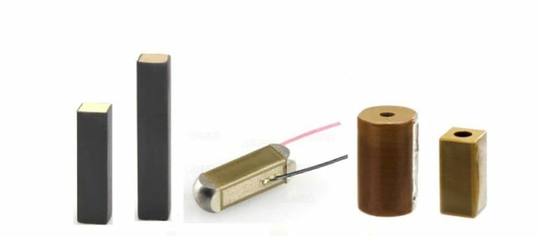
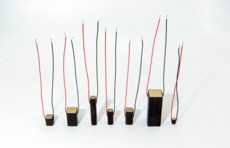
Piezo Direct’s multilayer piezo stack actuators are constructed with hundreds of inner electrodes and thin ceramic layers, which are sintered to form a monolithic stack actuator with a maximum single device height of 60 mm. Please note that discrete stacks can be built taller than monolithic stacks.
We offer a variety of multilayer piezo stack actuators. Shape, finish, material, dimensions, and performance levels can all be customized! Piezo Direct’s piezo stacks are suitable for numerous applications. Unsure what you need? Contact us! Piezo Direct is more than happy to work with you to design a custom piezo part to meet your application requirements. If none of these products match your requirements, click here to learn more about working with our engineers to build a custom piezo component.
- Applications
- Shapes
- Specifications
- Testing Method
Multilayer piezo actuators excel in applications requiring high precision, rapid response, and compact size. Their versatility makes them suitable for diverse industries, including:
Precision Motion & Control:
- Nano-positioning: Achieving sub-nanometer resolution for critical applications like semiconductor manufacturing and scanning probe microscopy.
- Precise Machining: Enabling ultra-fine control in material removal processes, leading to improved surface finish and dimensional accuracy.
- Piezo Positioning Stages: Building high-precision platforms for sample manipulation and measurement in scientific instruments and industrial automation.
- Microscopy & Imaging: Facilitating precise sample positioning and focus control for advanced imaging techniques.
- 3D Printing: Enhancing print resolution and accuracy through controlled micro-movements of the print head or stage.
- Linear Motors: Driving miniature linear motion systems with high force and speed, ideal for robotics and automation.
- Pumps & Valve Drives: Controlling fluid flow in microfluidic and other systems, crucial for lab-on-a-chip devices and medical applications.
- Optical Component Positioning: Precise alignment and manipulation of optical elements in telecommunications and photonics. Examples include:
- Add/Drop Multiplexers: Precisely selecting and routing optical signals.
- Optical Cross-Connect Switches (OXC): Dynamically configuring optical networks.
- Tunable Lasers: Adjusting the wavelength of laser light with high precision.
Medical & Life Sciences:
- Micro-pumps: Delivering precise volumes of fluids in lab-on-a-chip devices, drug delivery systems, and implantable medical devices.
- Piezo Valves for Drug Dispensers: Enabling accurate and controlled drug delivery, improving patient outcomes.
- Surgical Instruments: Enhancing precision and control in minimally invasive surgical procedures.
- Medical Imaging: Improving the resolution and speed of medical imaging systems.
Aerospace & Automotive:
- Thrusters: Providing precise control for small-scale propulsion systems used in satellites and unmanned aerial vehicles (UAVs).
- Active Trailing Edge: Improving aerodynamic performance through dynamic control surfaces on aircraft wings.
- Fuel Injectors for Common Rail Systems: Optimizing fuel delivery for improved engine efficiency and reduced emissions.
- Piezoelectric Injection Valves: Precise control of fuel injection timing and volume, leading to better engine performance.
- Vibration Damping: Reducing noise and vibration in automotive and aerospace systems.
Dispensing:
- Non-contact Dispensing: Accurate and repeatable dispensing of various fluids, including adhesives, inks, and chemicals. Applications include:
- Integrated Circuit (IC) Dispensing: Precisely applying adhesives or encapsulants during semiconductor manufacturing.
- LED Dispensing: Accurate dispensing of phosphor or encapsulant materials for LED packaging.
- Camera Module Dispensing: Precise dispensing of adhesives or sealants for camera module assembly.
- Inkjet Printing: Driving the print heads in inkjet printers for high-resolution printing.
Other Applications:
- Haptic Feedback: Creating realistic tactile sensations in electronic devices.
- Ultrasonic Transducers: Generating and detecting ultrasonic waves for various applications, including medical imaging and non-destructive testing.
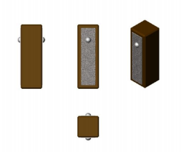
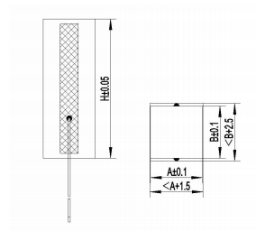
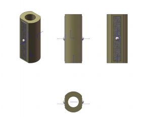
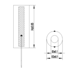
Please see the below images for accurate representations of this technology.



Multilayer Piezo Rectangular Actuators
Multilayer Piezo Ring Actuators
Multilayer Piezo Circular Actuators
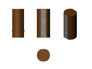
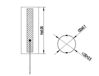
Multilayer Piezo Special-Shaped Actuators
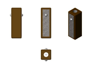
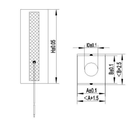
Custom Designs
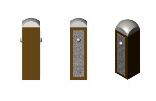
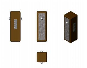
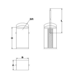
Specifications – Rectangular Actuators
PDJ150 Series for Rectangular Actuators – Max. driving voltage = 150VDC
| Model | Dimensions LxWxH [mm] | Nominal Displacement [µm@150V] ±10% | Blocking Force [N@150V] | Stiffness [N/µm] | Capacitance [µF@1V,1kHz] ±20% | Resonant Frequency [kHz] ±20% |
| PDJ1500303041 | 3x3x5 | 4 | 330 | 80 | 0.14 | 300 |
| PDJ1500303051 | 3x3x6 | 5 | 330 | 66 | 0.18 | 250 |
| PDJ1500303101 | 3x3x10 | 10 | 330 | 33 | 0.30 | 150 |
| PDJ1500302181 | 3x2x18 | 18 | 250 | 14 | 0.60 | 83 |
| PDJ1500303181 | 3x3x18 | 18 | 330 | 18 | 0.50 | 83 |
| PDJ1500505051 | 5x5x6 | 5 | 900 | 180 | 0.44 | 250 |
| PDJ1500505101 | 5x5x10 | 10 | 900 | 90 | 0.80 | 150 |
| PDJ1500505201 | 5x5x18 | 20 | 900 | 45 | 1.50 | 83 |
| PDJ1500505301 | 5x5x28 | 30 | 900 | 30 | 2.40 | 53 |
| PDJ1500505401 | 5x5x36 | 40 | 900 | 28 | 3.00 | 52 |
| PDJ1500505402 | 5x5x34 | 40 | 900 | 28 | 2.90 | 44 |
| PDJ1500505403 | 5x5x40 | 44 | 900 | 20 | 3.60 | 37 |
| PDJ1500505601 | 5x5x54 | 60 | 900 | 15 | 4.50 | 28 |
| PDJ1500707101 | 7x7x10 | 10 | 1800 | 1801 | 1.60 | 150 |
| PDJ1500707201 | 7x7x18 | 20 | 1800 | 90 | 3.00 | 83 |
| PDJ1500707301 | 7x7x28 | 30 | 1800 | 60 | 4.70 | 53 |
| PDJ1500707381 | 7x7x32 | 38 | 1800 | 47 | 5.30 | 47 |
| PDJ1500707401 | 7x7x36 | 40 | 1800 | 45 | 6.10 | 42 |
| PDJ1500707501 | 7x7x42 | 50 | 1800 | 36 | 6.90 | 36 |
| PDJ1501010101 | 10x10x10 | 10 | 3600 | 360 | 3.20 | 150 |
| PDJ1501010201 | 10x10x18 | 20 | 3600 | 180 | 6.00 | 83 |
| PDJ1501010301 | 10x10x28 | 30 | 3600 | 120 | 9.20 | 53 |
| PDJ1501010401 | 10x10x36 | 40 | 3600 | 90 | 12.00 | 42 |
| PDJ1501010501 | 10x10x46 | 50 | 3600 | 72 | 15.20 | 33 |
| PDJ1501010601 | 10x10x54 | 60 | 3600 | 66 | 18.00 | 28 |
| PDJ1501414101 | 14x14x10 | 10 | 7200 | 720 | 6.20 | 150 |
| PDJ1501414201 | 14x14x20 | 20 | 7200 | 360 | 13.10 | 75 |
| PDJ1501414301 | 14x14x30 | 30 | 7200 | 240 | 19.30 | 50 |
| PDJ1501414401 | 14x14x40 | 40 | 7200 | 180 | 26.20 | 37 |
PDJ200 Series for Rectangular Actuators – Max. driving voltage = 200VDC
| Model | Dimensions LxWxH [mm] | Nominal Displacement [µm@200V] ±10% | Blocking Force [N@200V] | Stiffness [N/µm] | Capacitance [µF@1V,1kHz] ±20% | Resonant Frequency [kHz] ±20% |
| PDJ2000303051 | 3x3x6 | 5 | 330 | 66 | 0.15 | 250 |
| PDJ2000303101 | 3x3x10 | 10 | 330 | 33 | 0.27 | 150 |
| PDJ2000505051 | 5x5x6 | 5 | 900 | 180 | 0.20 | 250 |
| PDJ2000505101 | 5x5x10 | 10 | 900 | 90 | 0.52 | 150 |
| PDJ2000505121 | 5x5x12 | 12 | 900 | 75 | 0.43 | 125 |
| PDJ2000505201 | 5x5x18 | 20 | 900 | 45 | 0.67 | 83 |
| PDJ2000505301 | 5x5x28 | 30 | 900 | 30 | 1.10 | 53 |
| PDJ2000505302 | 5x5x30 | 30 | 900 | 30 | 1.10 | 50 |
| PDJ2000505401 | 5x5x36 | 40 | 900 | 23 | 1.34 | 42 |
| PDJ2000505402 | 5x5x35 | 40 | 900 | 23 | 1.34 | 43 |
| PDJ2000707101 | 7x7x10 | 10 | 1800 | 180 | 0.69 | 150 |
| PDJ2000707201 | 7x7x18 | 20 | 1800 | 90 | 1.30 | 83 |
| PDJ2000707301 | 7x7x28 | 30 | 1800 | 60 | 2.00 | 53 |
| PDJ2000707381 | 7x7x32 | 38 | 1800 | 47 | 2.40 | 47 |
| PDJ2000707401 | 7x7x36 | 40 | 1800 | 45 | 2.60 | 42 |
| PDJ2000707501 | 7x7x42 | 50 | 1800 | 36 | 3.10 | 36 |
| PDJ2001010101 | 10x10x10 | 10 | 3600 | 360 | 1.50 | 150 |
| PDJ2001010201 | 10x10x18 | 20 | 3600 | 180 | 2.70 | 83 |
| PDJ2001010301 | 10x10x28 | 30 | 3600 | 120 | 4.30 | 53 |
| PDJ2001010401 | 10x10x36 | 40 | 3600 | 90 | 5.50 | 42 |
| PDJ2001414101 | 14x14x10 | 10 | 7200 | 720 | 2.80 | 150 |
| PDJ2001414201 | 14x14x20 | 20 | 7200 | 360 | 5.80 | 75 |
| PDJ2001414301 | 14x14x30 | 30 | 7200 | 240 | 8.60 | 50 |
| PDJ2001414401 | 14x14x40 | 40 | 7200 | 180 | 12.00 | 37 |
Specifications – Ring Actuators
PDH150 Series for Ring Actuators – Max. driving voltage = 150VDC
| Model | Dimensions OD/ID/H [mm] | Nominal Displacement [µm@150V] ±10% | Blocking Force [N@150V] | Stiffness [N/µm] | Capacitance [µF@1V,1kHz] ±20% | Resonant Frequency [kHz] ±20% |
| PDH1500525051 | Φ5/Φ2.5/6 | 5 | 600 | 120 | 0.3 | 250 |
| PDH1500525101 | Φ5/Φ2.5/10 | 10 | 700 | 70 | 0.5 | 150 |
| PDH1500525201 | Φ5/Φ2.5/18 | 20 | 700 | 35 | 1.0 | 83 |
| PDH1500845101 | Φ8/Φ4.5/10 | 10 | 1300 | 130 | 0.8 | 150 |
| PDH1500845201 | Φ8/Φ4.5/18 | 20 | 1300 | 65 | 1.5 | 83 |
| PDH1501006101 | Φ9.5/Φ5.5/10 | 10 | 1500 | 150 | 1.2 | 150 |
| PDH1501005101 | Φ10/Φ5.5/10 | 10 | 1500 | 150 | 1.2 | 150 |
| PDH1501205201 | Φ12/Φ5/20 | 20 | 3400 | 170 | 6.0 | 75 |
| PDH1501206101 | Φ12/Φ6/10 | 10 | 3000 | 220 | 2.4 | 150 |
| PDH1501206161 | Φ12/Φ6/16 | 18 | 3000 | 122 | 4 | 94 |
| PDH1501206201 | Φ12/Φ6/20 | 22 | 3000 | 100 | 5 | 75 |
| PDH1501304201 | Φ13/Φ4/20 | 22 | 3600 | 163 | 7.2 | 75 |
| PDH1502015051 | Φ20/Φ15/6 | 5 | 4000 | 800 | 1.4 | 250 |
| PDH1502619201 | Φ26/Φ19/18 | 20 | 7200 | 3600 | 14 | 83 |
PDH200 Series for Ring Actuators – Max driving voltage = 200VDC
| Model | Dimensions OD/ID/H [mm] | Nominal Displacement [µm@200V] ±10% | Blocking Force [N@200V] | Stiffness [N/µm] | Capacitance [µF@1V,1kHz] ±20% | Resonant Frequency [kHz] ±20% |
| PDH2001304201 | Φ13/Φ4/20 | 20 | 3600 | 180 | 4.6 | 74 |
| PDH2002015051 | Φ20/Φ15/6 | 5 | 4000 | 800 | 1.3 | 250 |
| PDH2002619201 | Φ26/Φ19/18 | 20 | 7200 | 360 | 7.7 | 80 |
| PDH2001304401 | Φ13/Φ4/40 | 40 | 3600 | 90 | 9.2 | 37 |
| PDH2002619351 | Φ26/Φ19/35 | 35 | 7200 | 205 | 15.3 | 43 |
High Pressure Series for Ring Actuators – Max. driving voltage = 1000VDC
| Model | Dimensions OD/ID/H [mm] | Nominal Displacement [µm] ±10% | Blocking Force [N] | Stiffness [N/µm] | Capacitance [µF@1V,1kHz] ±20% | Resonant Frequency [kHz] ±20% |
| PDH2501203201 | Φ12/Φ3/20 | 20@250V | 3500@250V | 175 | 4.6 | 75 |
| PDH2502515301 | Φ25/Φ15/30 | 30@250V | 9000@250V | 300 | 13.5 | 50 |
Specifications – Circular Actuators
PDY150 Series for Round Actuators – Max. driving voltage = 200VDC
| Model | Dimensions OD/H [mm] | Nominal Displacement [μm] ±10% | Blocking Force [N] | Stiffness [N/μm] | Capacitance [μF@1v,1kHz] ±20% | Resonant Frequency [kHz] ±20% |
| PDY15014241 | Φ14.2/24 | 24@150V | 7500@150V | 312 | 16 | 62 |
| PDY15014481 | Φ14.2/48 | 48@150V | 7500@150V | 156 | 30 | 31 |
| PDY15014201 | Φ14.7/20 2 | 20@150V | 7500@150V | 375 | 13 | 75 |
| PDY15014401 | Φ14.7/40 | 40@150V | 7500@150V | 188 | 27 | 38 |
| PDY20014051 | Φ14.2/6 | 5@150V | 7500@200V | 1500 | 1.4 | 250 |
Specifications – Special-shaped Actuators
PDT150 Series for Special-shaped Actuators – Max. driving voltage = 150VDC
| Model | Dimensions ID/ID/H [mm] | Nominal Displacement [μm@150V] ±10% | Blocking Force [N@150V] | Stiffness [N/μm] | Capacitance [μF@1v,1kHz] ±20% | Resonant Frequency [kHz]±20% |
| PDT150080804161 | 7.5×7.5/Φ3.5/16 | 16 | 1600 | 100 | 1.6 | 94 |
Remarks
- Measuring voltage range: 0 to150V and/or 0 to 200V and/or 0 to 1000V
- Recommended preload for dynamic operation: 15MPa
- Maximum preload for constant force: 20MPa
- Operating voltage: -20 to 150V DC and/or -20 to 200V DC
- Operating temperature range: -20° to 120°
- Wire lead, the red is for electrode (+) and the #333333 is for electrode (-)
*Customization available on request
*All specifications are subject to changes, please check with Piezo Direct before ordering
- The actuator must be placed vertically on a table and the table must be keCI level before testing. The test contactor must be set vertically on the table and keCI kept in contact with the center of top of the actuator during testing.
- Only DC voltage should be applied
- The red lead wire is the positive (+) and the #333333 lead wire is the negative (-).
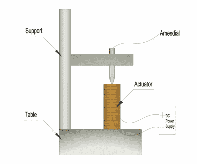
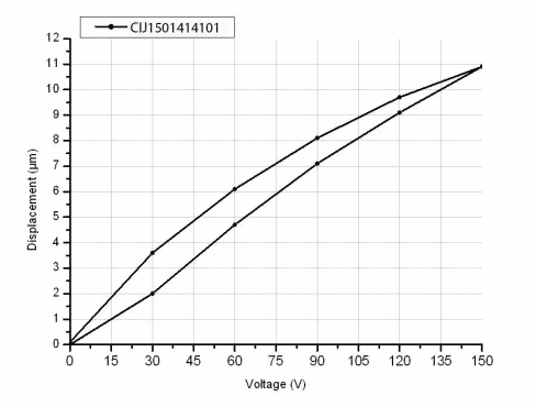
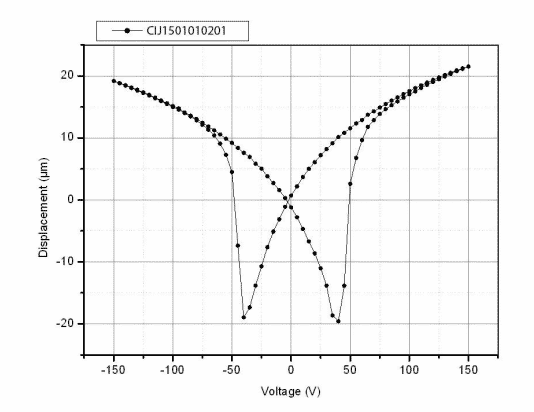
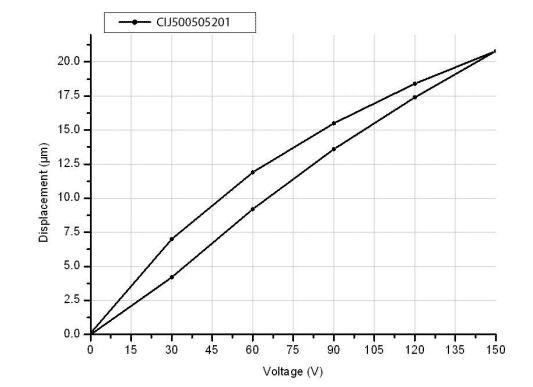
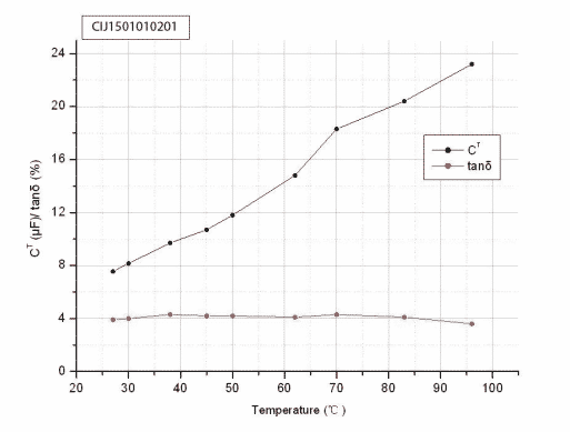
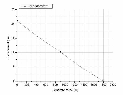
Testing Curve

Mount and Connect
- The actuator should be connected in-line with the element, and be driven by rigid connection.
- No load is prohibited. Please apply 20Mpa preload if response time is below 100μs. Please refer to the tables below for details.
- Do not apply a voltage exceeding max. driving voltage value to the actuator
- The actuator should be used in a dry atmosphere below 75% RH and in a range of temperature -20~120℃ Otherwise, a drop in insulation resistance or shortened working life may occur.
- The resin-coated type of actuator is weak to a tensile force because of its structure. As a result, the direction of the generated force must be the same as the center axis of the actuator. Please see the examples shown below.
Preload Force for Rectangle Actuators
| Length [mm] | Width [mm] | Normal Pressure [MPa] | Max. Pressure [MPa] | Proposal Preload Force [N] | Max. Preload Force [N] |
| 3 | 3 | 15 | 20 | 135 | 180 |
| 5 | 5 | 15 | 20 | 375 | 500 |
| 7 | 7 | 15 | 20 | 735 | 980 |
| 10 | 10 | 15 | 20 | 1500 | 2000 |
| 14 | 14 | 15 | 20 | 2940 | 3920 |
Preload Force for Ring Actuators
| Length [mm] | Width [mm] | Normal Pressure [MPa] | Max. Pressure [MPa] | Proposal Preload Force [N] | Max. Preload Force [N] |
| 5 | 2.5 | 15 | 20 | 220 | 300 |
| 8 | 4.5 | 15 | 20 | 510 | 690 |
| 10 | 5.5 | 15 | 20 | 820 | 1100 |
| 12 | 5 | 15 | 20 | 1400 | 1870 |
| 12 | 6 | 15 | 20 | 1400 | 1870 |
| 10 | 5.5 | 15 | 20 | 700 | 940 |
| 20 | 15 | 15 | 20 | 2060 | 2750 |
| 13 | 4 | 15 | 20 | 1800 | 2400 |
| 26 | 19 | 15 | 20 | 3700 | 4950 |
| 12 | 3 | 15 | 20 | 1590 | 2120 |
| 25 | 15 | 15 | 20 | 4710 | 6280 |
| Outer Diameter [mm] | Normal Pressure [MPa] | Max. Pressure [MPa] | Proposal Preload [N] | Max. Preload [N] |
| 14.2 | 15 | 20 | 2400 | 3200 |
| 14.7 | 15 | 20 | 2500 | 2400 |
Preload Force for Special-Shaped Actuators
| Length [mm] | Width [mm] | ID [mm] | Normal Pressure [MPa] | Max. Pressure [MPa] | Proposal Preload [N] | Max. Preload [N] |
| 7.5 | 7.5 | 3.5 | 15 | 20 | 700 | 940 |
